KB9JJA’s Building of Scotty’s 0 - 3 GHz Spectrum Analyser
This project has got to be the ultimate build for anyone interested in electronics and home brewing equipment. It was initially designed by Scotty Sprowls a retired RF engineer, many refinements and additions have been made over the years, by the group of builders. Most notably Sam Wetterlin who also maintains a site dedicated to the the MSA
These pages are a collection of notes to my self. Some of the info presented here are clipping from the builds group mailing list. I tried to quote the sources of information when I could.
The main MSA web site can be found at www.scottysspectrumanalyzer.com
Sam Wetterlins site can be found at www.wetterlin.org/sam/
- My Notes on various SLIM Modules
- My Notes on the SA Filters
- My Notes on The Filter Plus Group buy put together by Jim W1JGH from Feb 2011
I have been watching this project for a few years with great interest, and finally decided it was time to build it.
Boards:
I put a note out on the message board, seeing if anyone had a full set of boards for sale. I received a few responses with in a few days, and I purchased a set of boards from a gentleman that had a spare set from one of the group purchases earlier in the year.
This is the set of boards that I received.
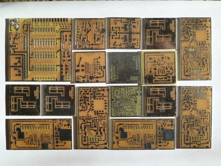
Basic Set of Slim SA Boards
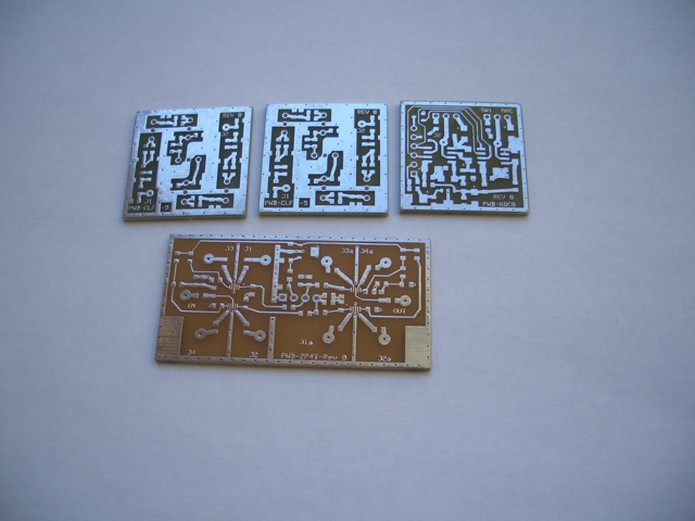
Additional boards included
So the hunt for all the parts gets started.
I started compiling a list of needed parts in excel from the BOM of all the modules on the web site. There were parts that are no longer available, so I had to do a little research on acceptable substitutes. A Copy of my spread sheet is here, No guarantee of its accuracy. (I know the 5 volt regulator count is wrong, I ordered extras and did not take the time to go back and fix it.)
I have a good supply of parts in the shop, but my supply of surface mount parts is small. Still some I had on hand. With the exception of the min Circuits parts, all of the passive and active components were ordered from Digikey.
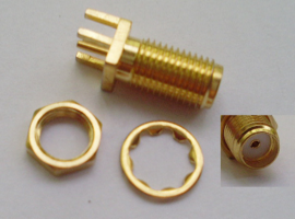
I have been using these SMA connectors in the shop for some other projects. I ordered 40 more for the SA projects. They are extra long and come with the mounting nut. The circuit board pins are cut off and filed smooth for use with the SLIM modules. I purchase them on ebay. From APACE-Electronic out of Hong Kong they were 20 for $17.00 shipped.
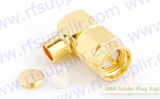
I also ordered 30 Male Right Angle connectors from rfsupplier.com which I found on e-bay.
I ordered 1 Meter of Coaxial Semi-Rigid Cable Flexible RG402 .141" 50 ohm From ebay also.
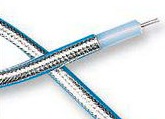
With what I have on hand, as well as what I have ordered I should have most of the interconnects for the SLIMs as well as the cable for the cavity filter.
This will deplete my SMA stock, so I will probably keep looking for a few more connectors on ebay.
Filters:
The SA is designed with a variable IF, as a DDS is used for the LO so it can be adjusted. This allows for a variable IF based on the width of the cavity filters. It should be about 2 Megs wide.This allows the final 10.7 MHz filters to fall out side the normal 10.7 Mhz. Gigikey had some 10.738635 MHz crystals. I ordered 30 so I could match some up for the home built narrow crystal filters.
I also found some 10.7 Mhz filters for sale from Barry VE6SBS on his web site http://4sale.sbszoo.com/crystals.htm#filter
I purchased The following filters from him at a very reasonable price. 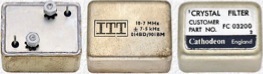
Cathodean 10.7 Mhz filters (1 Each)
FC03234 is 18KHz - 6 pole
FC03200 is 18KHz - 4 pole
FC03205 is 35KHz - 4 pole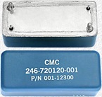
I also ordered 3 CMC Filters (3 Each)
10.7 MHz - 15 KHz BW
He also had a GRE SSB filter listed on his site. It was listed as GRE FEC-113-4 SSB for 11.2735 Mhz, but he had no other info. For $10.00 I thought I would take the chance and order it to see what I wind up with.
Two narrow filters will also be required for use in the SA. I plan on building them with the 10.738 Mhz crystals I ordered from Digikey.
Controller Board:
2-3-2011
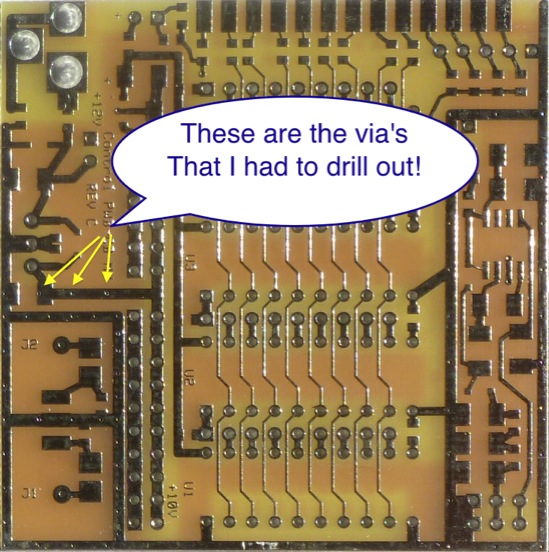
I built the controller board first. Everything went together well, but when I powered it up it was drawing way too much current, and my bench power supply folded the voltage way back. I disconnected it and discovered that the output of the 10 volt regulator was shorted to ground. I spent the rest of the evening looking for the short. I finally noticed that there were some extra via’s in the output of the 10 volt regulator that went directly to ground! My board is marked RevC, but I did not see any engineering notes on Scottie’s web site. Not could I find anything on the list server.
I drilled them out with a small drill bit tested the board. All checks out OK
2-6-2011
Soldered up a bunch of the boards, based on the parts I have on hand.
SLIM-MO-64, SLIM-DDS-107(2), SLIM-PDM, SLIM-ADC-16, SLIM-LD-8306, and SLIM-IFA-33. All are together less the Mini-Circuit parts.
2-8-2011
Built and tested the 16 bit Analog to Digital Board. I had a short on this board due to some of the parts moving around when I soldered them. I did not notice them when I built the board.
The error most likely put 10 volts on pins 9 and 10 of U3. I fixed the problem with the parts, and started testing. Voltage readings are all good now.
Mag Volts for IC U2 tested good following the procedure on the web page. I ran into problems when I started testing U3 Phase Volts. The input to U3 floats around a bit, and I could not get the voltage to drop to zero using the volt meter as a voltage source. I wired up a potentiometer and can get the trace to go to the top or bottom when applying 5 volts or 0 volts, but it still acts odd when I remove the voltage. I removed C21 from the circuit, but the input still is acting up. Pulling the chip and re-soldering it did not make a difference. I think I hurt the chip when the parts shifted around during initial soldering. I will have to order a new AD7685 to replace U3.
I am deviating from the build and test procedure recommended on the web page, based on parts I do not have on hand yet. I am waiting on my order from Mini-Circuits, and another from Digikey for parts I missed on my first order, or were out of stock.
2-11-2011
Found and ordered a bunch of Crystal filters today.
Tested DDS1 DDS3 and the Master Osc board. All tested out OK.
2-12-2011
Moved my Notes pages, to a separate web page. Also started collecting info on the group buy that is going on for the extra boards, so I do not have to search back through the archives for the related info on them.
Received an e-mail from the gentleman that purchased the boards from. It turns out that the boards were from an order he placed with the board manufacture, and not from a group buy. He was very apologetic and even took the time to search the gerber files on the other boards for extra via’s, of which he did not find any.
I also received an e-mail from Jerry on the list about having a surplus of 10.11 MHz crystals. So I will have some of those to play with also.
Searched e-bay for SMA cables and connectors. Wound up ordering a meter of coax and 20 connectors. This will allow me to make the cables the length they need to be.
Started wiring up the control harness for the SA. I had lots of connectors in my junk box that I am using. For the control board side I am using female .1 headers and soldering the wires to them. The SA is being built in a test grid of cut circuit board material. Once I have it working I will add shielding and build a proper mounting system for the SLIMs.
I will try to get some photos up of my setup tomorrow.
2-16-2011
My replacement ADC receiver came today, as well as my Mini Circuits Order.
I cam home from work with a fever so did not get to work on the MSA
2-17-2011
Was home again today with a fever, so I worked from home.
10.11 Mhz Crystals came in the mail today.
Received an e-mail that my Crystal filters shipped from Canada.
Did get the new ADC converter installed on the Phase side, It is a little more stable but it does not respond to the volt meter test as fast as the Mag side.
I played with it a little, changed the transistor on the Phase side. Did not make a difference.
I tested all the traces on the board and everything checked out fine.
Not sure what is going on, but I am pressing on with my testing for now.
Sent a message to the group to see if anyone has any idea on why the phase side moves so slow.